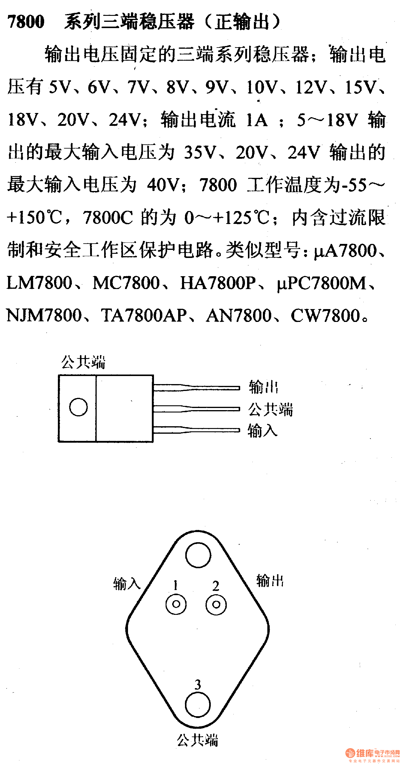

I also connected a 3K resistor from pin 3 of the 7805 to pin 2, to provide bias current for the series diodes, but the resistor value is not critical, as long as a few mA of current flows through the diodes independent of current from pin 2 of the 7805. I believe I used 3 diodes, as the series combination had a voltage drop of about 4 volts, though it isn’t important to use 3 all that matters is that the series forward voltage drop is, in this case, 4 volts (I measured the forward voltage drop of each diode, selecting from a larger quantity of diodes, ones that fit my need, that is, those that yielded a total forward voltage drop of four volts).

The diodes are connected cathode to anode, so they will conduct when properly biased by a DC voltage/current, and the anode of the first diode in the series string is connected to pin 2 of the 7805. I solved this problem by using the 7805 in place of the 7809, but, I placed several rectifier diodes (of the 1N400X family, but others will work as well) in series with the 7805 GND (pin 2 in your schematic) pin, that is, between pin 2 and the negative side of the power supply. I needed the power supply right away, and there is no local source for the 7809. I did not have a 7809 regulator, but I have hundreds of 7805’s left from my old company. I have also made power supplies using this method, virtually identical to your schematic, with one difference.


 0 kommentar(er)
